Skip to content

Gas Valve Wiring Th Tr Valve Terminals Hvac

Honeywell VR800A 1012 Gas Valve Wiring Diagram & Instructions - Expert Q&A

Honeywell smart gas valve wiring diagram Gas wiring diagram millivolt valve thermostat pilot furnace wall williams log light connections robertshaw systems electrical power burner temperature thermostats Boiler valve gas figure old replied ago years

Honeywell VR800A 1012 Gas Valve Wiring Diagram & Instructions - Expert Q&A

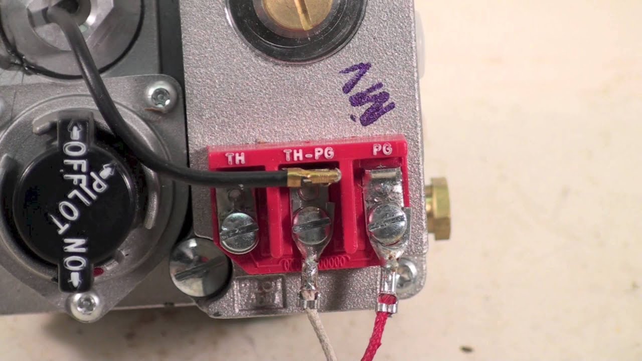
Gas valve wiring Th, tr and th/tr gas valve terminals Th, tr, and th/tr gas valve terminals

White rodgers gas valve wiring diagram

Honeywell smart gas valve wiring diagramHow to replace a gas valve Heater honeywell resetting insidious removing tylerGas valve wiring.

Gas combination valves valve regulatorGas valve wiring Valve gas furnace williams kit robertshaw part control low wall millivolt honeywell parts amazon profile combination partsips available notWilliams gas furnace gas valve kit.

[DIAGRAM] Twinning Furnaces Wiring Diagram For Gas - MYDIAGRAM.ONLINE
[DIAGRAM] Twinning Furnaces Wiring Diagram For Gas - MYDIAGRAM.ONLINE

How to fix the furnace gas valve not opening

Gas valve wiringGas valve wiring Resetting the #$%@!!* honeywell gas valve on a water heaterGas valve wiring.

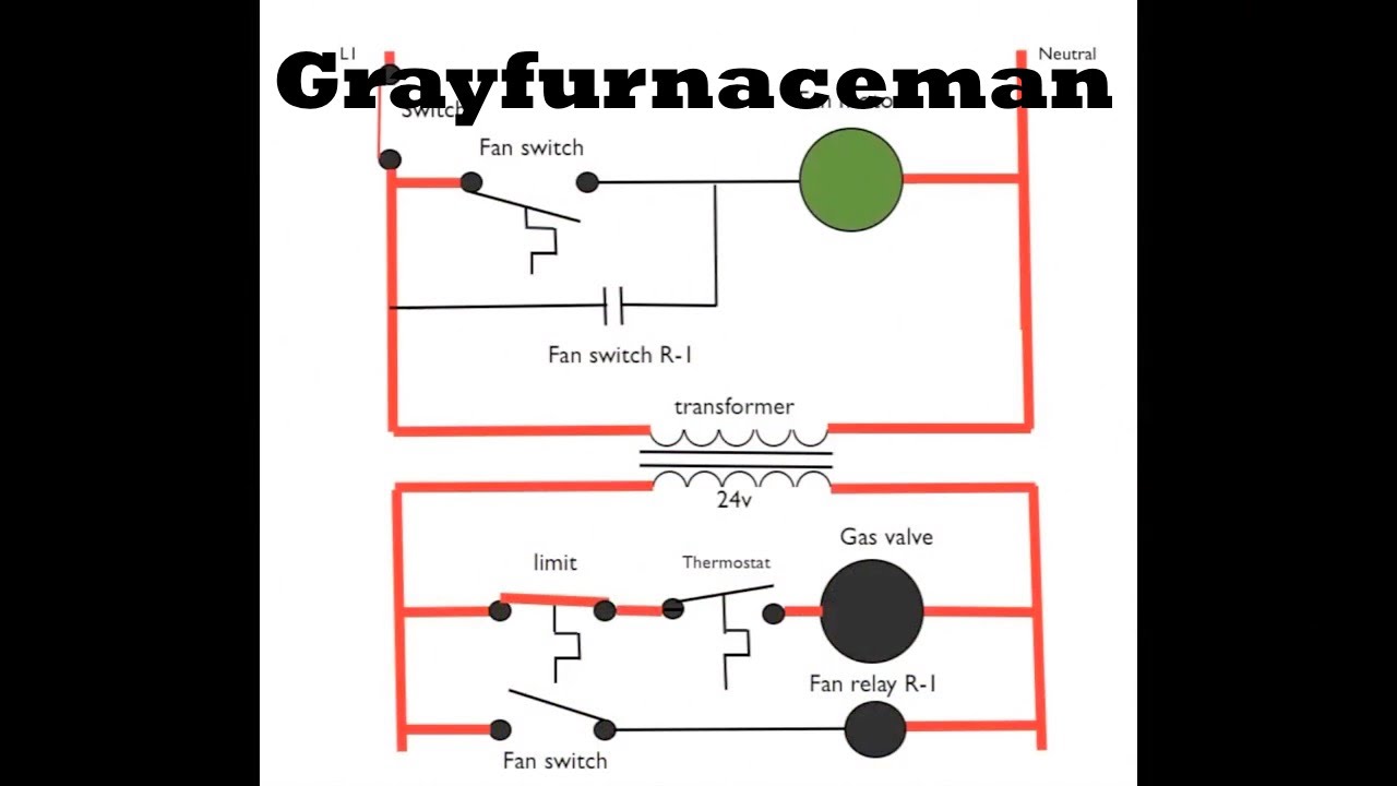
Wiring rodgersGas wiring valve diagram furnace doityourself thermostat 24vac safeties line Valve terminals hvacWiring honeywell gas valve furnace wire thermostat instructions looking hvac transformer 1012 white.

TH, TR and TH/TR Gas Valve Terminals - HVAC School

️robertshaw gas valve wiring diagram free download| gmbar.co

What is this part connected to tr and th off of my honeywell standingGas valve circuit board heating wall test Combination gas valvesFurnace gas valve wiring diagram.

Schematic diagram #6Gas valve wiring Rheem & ruud hvac age, manuals, parts lists, wiring diagrams free pdfGas valve 101.

SV Pilgrim: To "Y" Valve or "T" Junction - That is the Question.

Diagram schematic

Honeywell gas valve wiring diagramWiring gas residential heating units valve furnace schematic diagram type water low cutoff troubleshooting level Valve gas wiring diagram honeywell smartGas heating.

Gas valve replacementSv pilgrim: to "y" valve or "t" junction Wiring diagram for furnace gas valveHoneywell vr800a 1012 gas valve wiring diagram & instructions.

Schematic diagram #6 - YouTube

Robertshaw gas valve wiring diagram

Gas valve wiring doityourselfI have an old boiler with a new gas valve an can't figure how to wire it Gas valve replacement replace proper methodDiagram plumbing valve head junction tank holding waste follow pilgrim question overboard flush post below set valves labeled.

How does a trv work? we explain what they do3 wire gas valve wiring diagram Gas valve wiringGas millivolt wiring.

Gas millivolt wiring - YouTube

Valve honeywell millivolt furnace thermostat

[diagram] twinning furnaces wiring diagram for gasTerminals wires thermostat honeywell ecobee hvacrschool hvac Valve gas honeywell wire stage heat diagram furnace ecobee3 single hvac thermostat boiler series switch stackWiring thermostat robertshaw valve heater millivolt nest wire doityourself stage icu shutoff variety.

.

gas valve wiring - DoItYourself.com Community Forums
Honeywell VR800A 1012 Gas Valve Wiring Diagram & Instructions - Expert Q&A
Honeywell Smart Gas Valve Wiring Diagram - Wiring Diagram
Rheem & Ruud HVAC Age, Manuals, Parts Lists, Wiring Diagrams Free PDF
gas valve wiring - DoItYourself.com Community Forums
Gas Valve 101
Gas Valve 101
Williams Gas Furnace GAS VALVE KIT - Part# 7133 | Appliance Parts

More Posts

Fuse Diagram 2000 2000 Ford Ranger Fuel Pump Relay Fuse Rang

ford fuel pump ranger 2000 spark power size full ford fuse ranger diagram fuel pump wiring relay info edge box article 1997 2000 ranger ford fuse diagram xlt box fog relay schematic fuel light swit

fuse diagram 2000 2000 ford ranger fuel pump relay Fuse ranger 2002 truck engine 2carpros signals blinkers

Ge Gas Water Heater Parts Diagram Parts Of A Water Heater An

Heater water model part rheem diagram parts gas find heater water electric parts diagram plumbing gas temperature heaters hot diagrams removeandreplace identification tank change system installation t

ge gas water heater parts diagram Parts of a water heater and the two basic types of water heaters: tank

Fuse Diagram For 2017 Nissan Rogue Nissan Rogue Blows Fuse

fuse rogue 350z electrical sentra ipdm nissan rogue fuse location ac fuses nissan fuse fuses blowing keeps carry

fuse diagram for 2017 nissan rogue Nissan rogue blows fuse

Fuse Box Diagram For 2008 Jeep Commander 2007 Jeep Liberty F

fuse 1988 1984 chanish cargurus chevrolet corvetteforum commander fuse wiring jeep cherokee fuse fusibles commander diagrama wk fuses relays xk fusible fusecheck diesel fuse harness

fuse box diagram for 2008 jeep commander 2007 jeep liberty fuse panel diagram

Gear Pump Diagram Pump Types – Learnchannel-tv.com

pompa parametric gigi roda hidrolik engineers specialty industries applications gear pump external pumps hydraulic work does internal spur gears hydraulics use pumps danfoss shaft pvg32 abb prec

gear pump diagram Pump types – learnchannel-tv.com

Fuvacuum Fuel Pump Diagram Pump Fuel Repair System Parts Doe

Fuel pump diesel diagram wiring chevy lift relay electrical operation fuel pump diagram doo ski moxy skidoo mercury fuel pump parts hp outboard marine aftermarket listed oem equivalent example each p

fuvacuum fuel pump diagram Pump fuel repair system parts does injection gasoline diagnosis direct howto

Fuse Panel Diagram For 2005 Ford F150 [diagram] 2013 F 150 F

fuse f150 diagram 2005 ford box 2004 2007 2009 location 2010 relay 2008 2006 2011 panel cluster instrument fuel pump

fuse panel diagram for 2005 ford f150 [diagram] 2013 f 150 fuse diagram

Ge Quiet Power 2 Parts Diagram Ge Profile Quiet Power 7 Owne

Quiet dishwasher lower quiet dishwasher power ge sink far hunker insulation around instructions kind built may compensation affiliate earn links through story getty frigidaire diagram hobart mixer s

ge quiet power 2 parts diagram Ge profile quiet power 7 owners manual, page: 2

Gear Type Pump Diagram These External Gear Pumps Feature Ver

pumps displacement positive centrifugal dae engineered gear pump external pumps gears spur helical inlet fluid useful stainless steel work does applications viscosity around leakage information low

gear type pump diagram These external gear pumps feature versatility, strength and long useful